
Emissive and Masked Materials
Uniform Material Parameters
A few months ago I built a rendering pipeline that defined:
- Shader: a specific algorithm used to draw a surface (applying lights, etc.)
- Material: a specific configuration of a shader (deciding albedo, normal, roughness, etc.) through textures or uniform parameters.
This architecture was iterated on recently, with the purpose of:
- supporting new types of shaders (e.g. emissive)
- making failures less likely (e.g. missing textures fallback to solid color)
- having the engine "understand" materials
This last point is what this section is about. In the previous architecture the shader was entirely responsible for defining its material configuration (textures and uniform parameters). Therefore, since a shader is game-specific, no engine code could define how a material is loaded nor how it can be updated live for debugging purposes.
Last week mostly handled textures, this week handled uniform parameters (especially useful for emissive materials since they need intensity scaling). I'll pass on the details as it's only about architectural decisions, just know that:
- The game shader defines a list of uniform parameters (name, type, default value)
- The game material can override them by name
- At runtime and for each shader, the engine code builds a buffer layout (see bonus section at the end) to communicate from CPU to GPU
This involves a lot of boilerplate and shader codegen, but it unlocks a nice debugging feature:
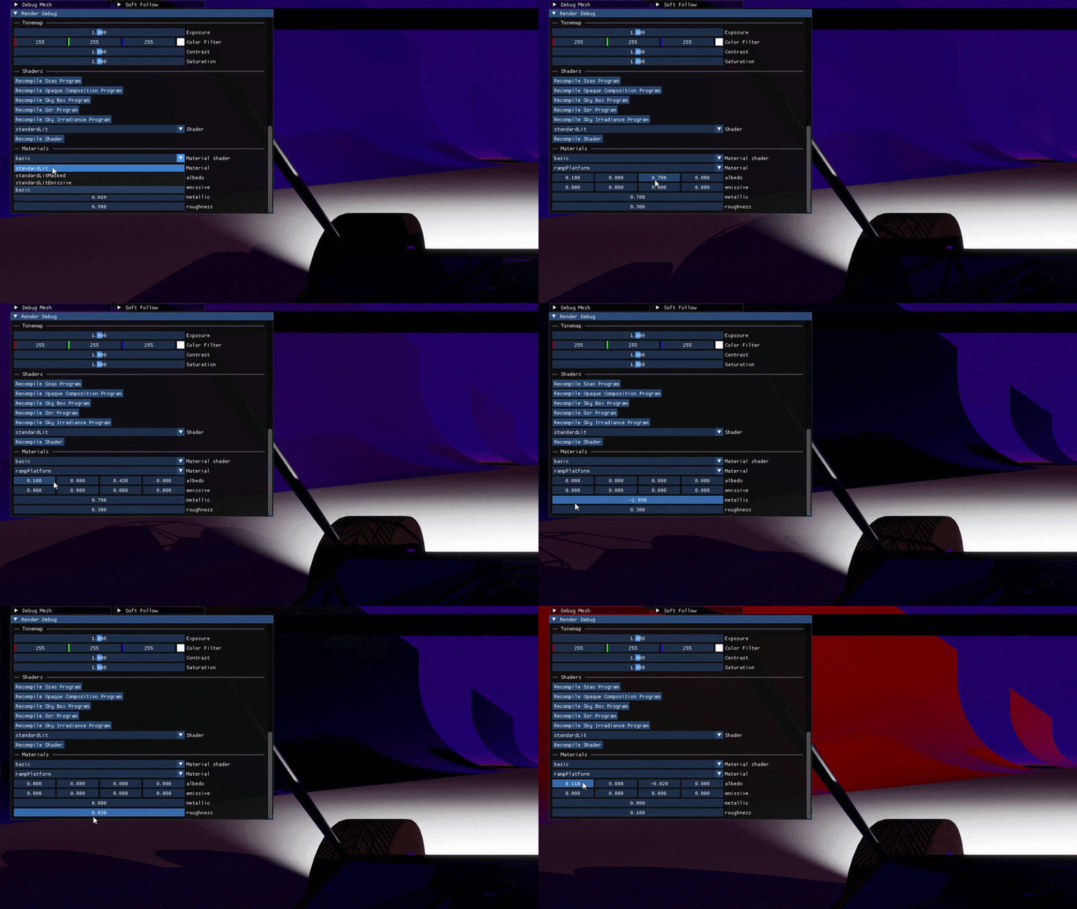
Sadly, gifs compress the reflection of the sky on this surface, but know that it's beautiful on my screen.
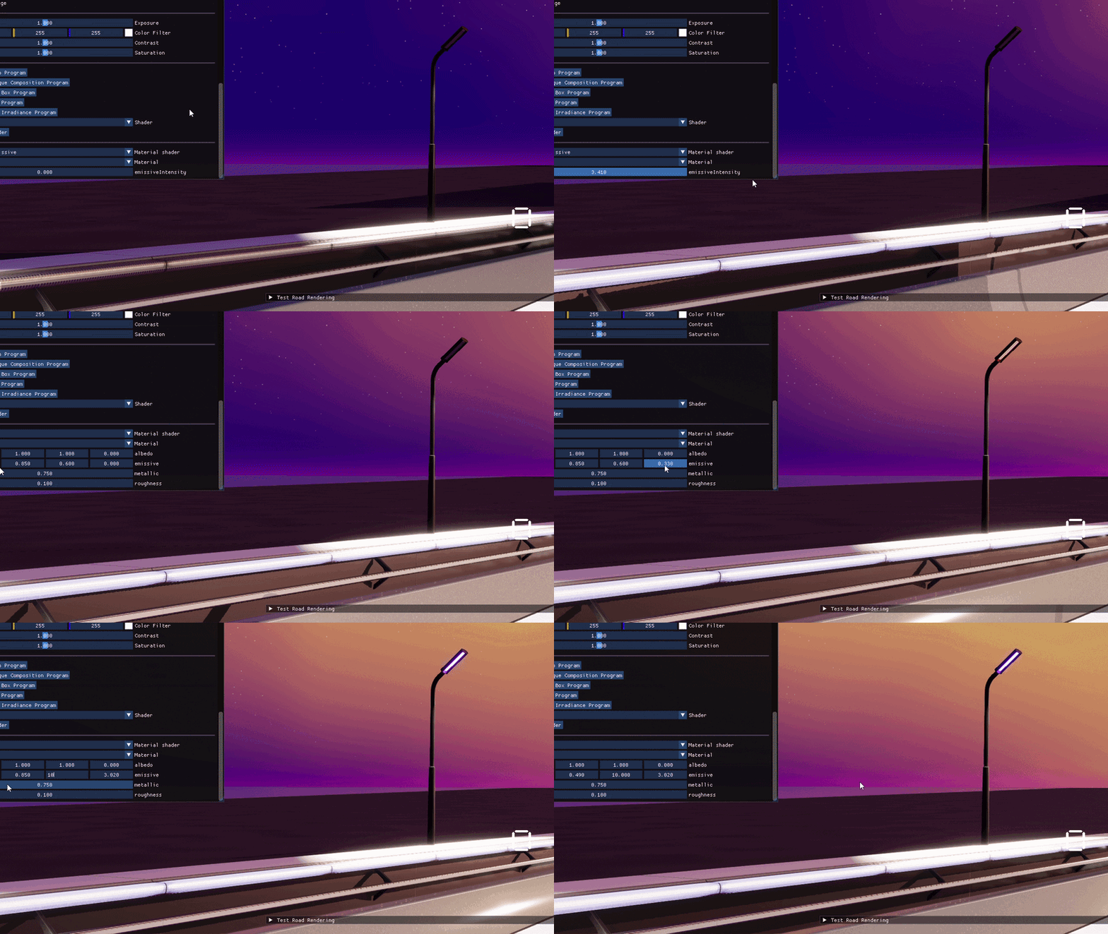
And of course this unlocks emissive materials (`pixelColor = applyLightTo(albedo, normal, metallic, roughness) + emissive * uniformEmissiveIntensity`):
Screen Space Reflection v3
Improving Reflection Behind Objects
As explained a long time ago SSR works by raymarching through the depth buffer. However the depth buffer only captures what the camera can see: any surface hidden behind another is unknown.
It means that when the ray passes behind the front-most element displayed on screen (without really going through it), the algorithm must decide if the ray should be blocked or allowed to continue.
Around 2:45 to 3:00 in the video below you can see what happens when the algorithm decides to let the ray continue after it passes behind a blocker: it looks like the car is just a cardboard piece and the reflection over the ice is broken.
This is why I implemented a heuristic to decide to block or let go the ray based on how deeply the ray penetrated behind the blocker. It's clearly imperfect but it improves rendering a lot.
Yes the video is all over the place because I forgot to record a before-after properly.
Redoing Ray Marching
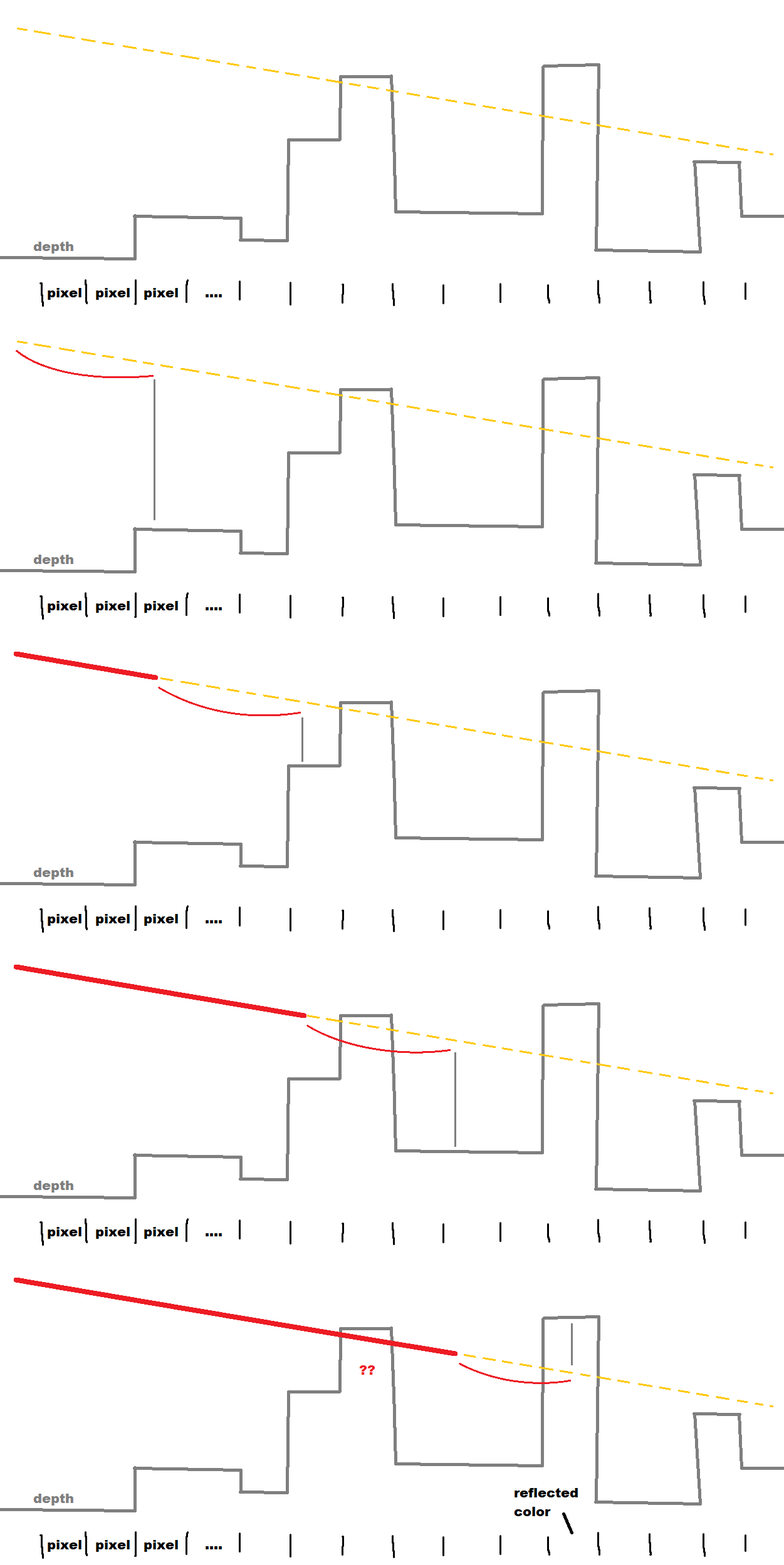
The naive algorithm I had implemented was performing steps of fixed length through the depth buffer until it found something to hit, thus deciding the reflected color (I simplify, there were also smaller steps performed at the end to improve precision of the reflected image). The issue is that, to have good reflections you want the fixed length to be short (ideally 1 pixel at most per step so no blocker is missed) but this hurts performance a lot.
Here is the naive algorithm simplified:
You've probably seen it a million times in my videos, but here is another one showcasing the jagged silhouette this imprecision produces:
It turns out there is much better that can be done to find the perfect pixel to reflect while keeping performance acceptable:
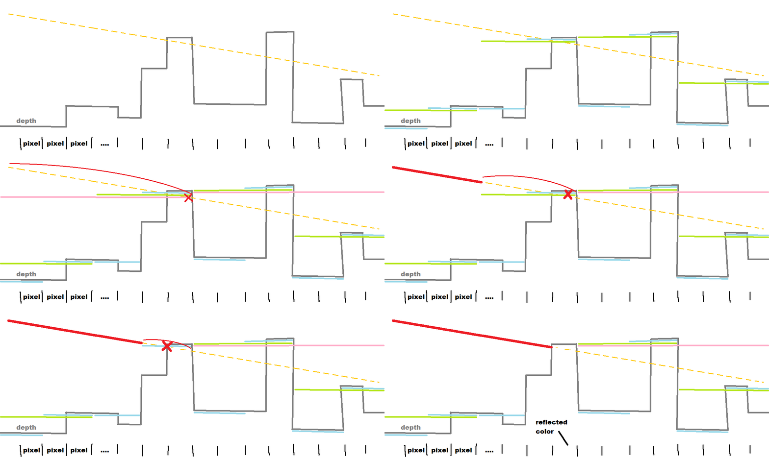
1. compute a hierarchical depth buffer: smaller and smaller versions of the depth buffer where each version stores, for each pixel, the closest distance of the 4 pixels of the version above it.
2. now each ray can walk on the smaller depth buffer (big steps, fast) until they are blocked and then "look closer"
Here is how it works, animated:
And after a few hiccups implementing the algorithm...

... here is what it looks like now:
About 5% performance gained while looking better?
Alpha-Masked Materials
My last 2 weeks' work on shaders and materials also unlocked a new type of material: alpha-masked materials.
In short, it's a type of opaque shader (so not a shader to render translucent objects) that discards pixels whose transparency value (`1-alpha`) would be above a given threshold (usually the values would come from an albedo texture with an alpha channel).
There was still a lot of engine fixes necessary to make this work (tldr; my depth pre-pass and shadow shaders were shared programs between all opaque surfaces which wouldn't work for a surface using an alpha-mask) but here are the results:
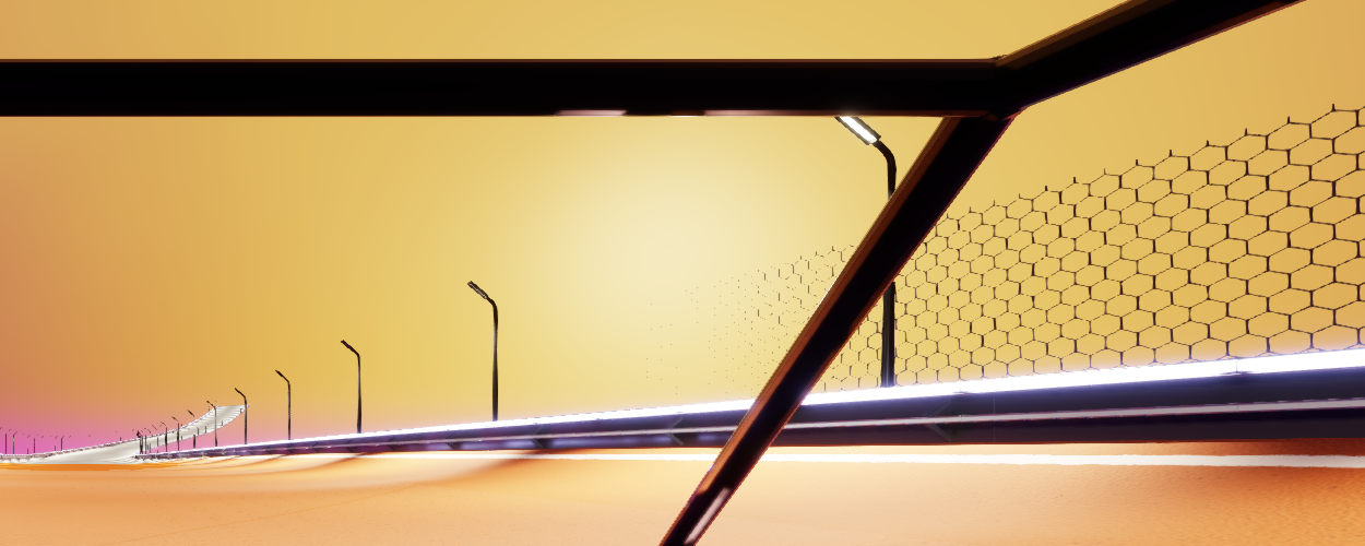
Arf... you see it too? the fence disappears after a very short distance! This is because my automatically-generated mips (smaller LOD versions of the texture to make it look nicer from afar) blur the alpha channel such that all pixels eventually fall below the transparency threshold.
This is a very common issue usually solved by alpha-coverage preserving: it means generating mips while tweaking pixels' alpha value to preserve the ratio of pixels below and above the threshold. This process can be tuned, here is the result of two attempts:
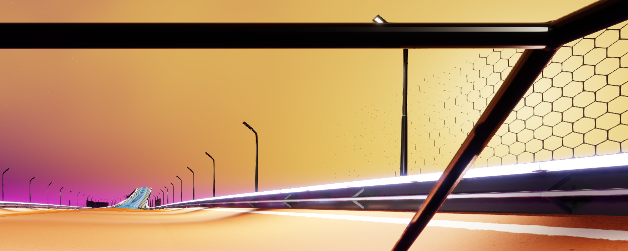
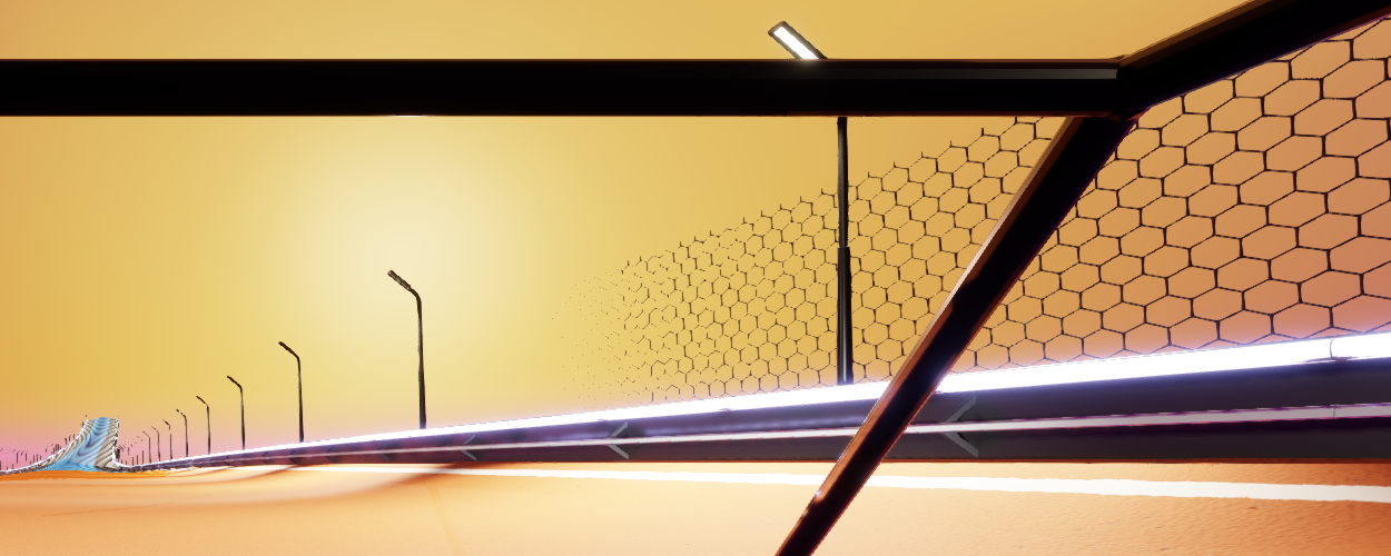
It's slightly better, the fence being visible a bit farther, but still too sparse while sometimes letting the fence become fully opaque at a distance (2nd image).
Additional solution: decaying alpha. Since, for such a fence, the number of opaque pixels is pretty low, I can slowly increase the ratio of opaque-to-transparent pixels as the LOD increases (so for far objects).
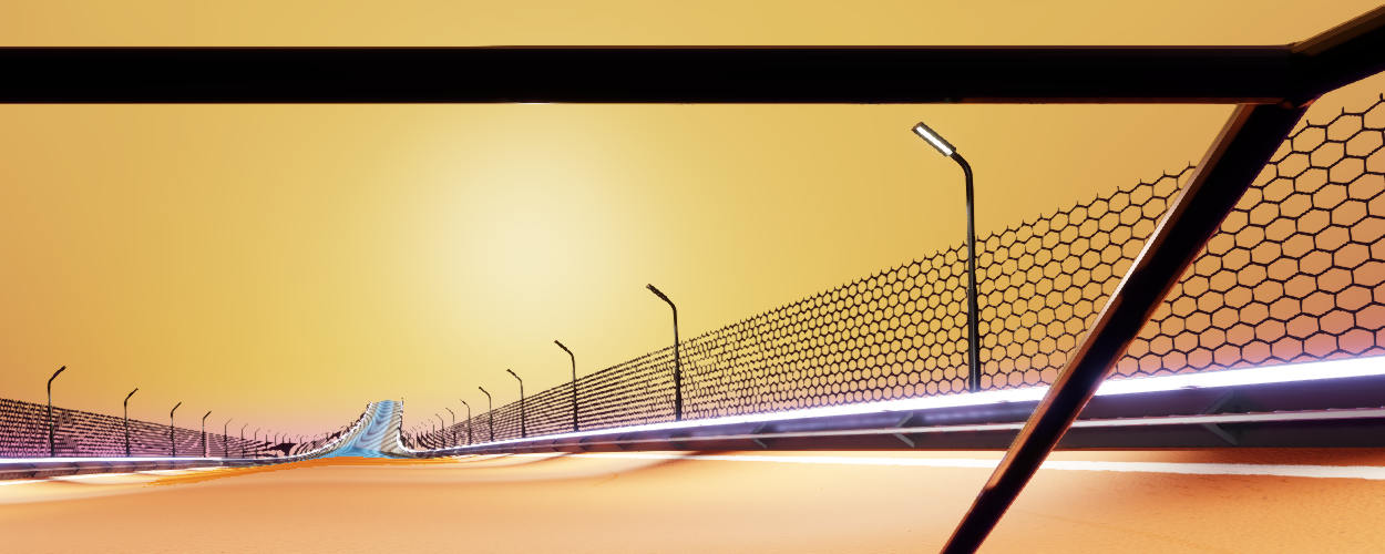
Better, but there is still room for improvement: first it makes the fence become thicker at a distance, second it makes some tiling artifacts appear far from camera again. Frankly there is no magical solution, or I would have to make the fence become transparent at a distance.
...
Joking! there is somewhat of a magical solution: stochastic threshold! Instead of ignoring every pixel whose alpha value is below a fixed threshold, use a random threshold per pixel. This completely eliminates the need to mess around with mips (auto-generated ones work) as, statistically, there should still be the same proportion of pixels being drawn on screen. However (that's where the magic ends) the result is then noisy, which would be solved (in the future) by temporal anti-aliasing:
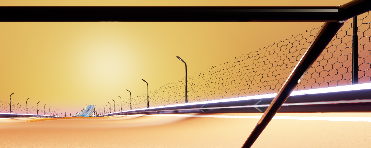
And here it is animated (it looks much better while driving already):
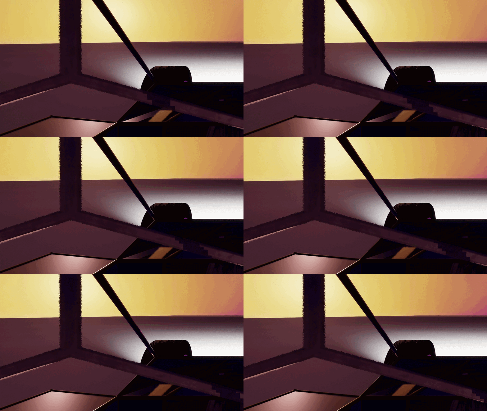
----
Bonus
Blooper
Not really a blooper, I just thought it was cool driving while displaying only reflected colors (what the SSR builds):
Shader Parameters Layout
I skimmed through this earlier, but imagine a shader needs its materials to provide the following:
- vec2 uvScroll
- vec3 albedoColor
- vec2 anisotropyDir
- vec4 emissiveColor
- float roughness
Previously the game programmer (me) was responsible for creating a structure with correctly aligned and ordered properties because GLSL / OpenGL has strict constraints on how they can be provided to the GPU by the CPU:
- vec4 uses 16 bytes and must align over 16 bytes
- vec3 uses 12 bytes and must align over 16 bytes
- vec2 uses 8 bytes and must align over 8 bytes
- literals such as float/int use 4 bytes and must align over 4 bytes
Meaning, with the above example (80 bytes), a perfectly packed order (48 bytes) could be:
- vec4 emissiveColor
- vec3 albedoColor
- float roughness
- vec2 uvScroll
- vec2 anisotropyDir
Now the game programmer (still me) only instantiates a generic structure at runtime —possibly loaded from an asset— that contains a list of parameters (names, types, and default values ... Unreal's material parameters, anyone?), and of course writes the shader code using uniform values with such defined names.
The engine code then, at runtime, creates a layout with those parameters ordered (roughly: vec4 comes first, then pairs of vec3 and literals to fill 16 bytes exactly, then all vec2, and finally the remaining literals) and injects this same layout into the user's shader code so both CPU and GPU agree.